How VOCs affect air quality, health and the environment – Part 1

The term VOC (Volatile Organic Compound) refers to a wide range of carbon-containing chemical compounds. At room temperature, VOCs tend to be liquid or solid, with a high vapour pressure that means they readily vaporise into gaseous states. In recent years, increasing attention has been paid to VOCs as pollutants and health hazards. This blog will provide an introduction to VOCs and their effects on human health and the environment, and give an overview of regulations on VOC emission.

Sources of VOC in air

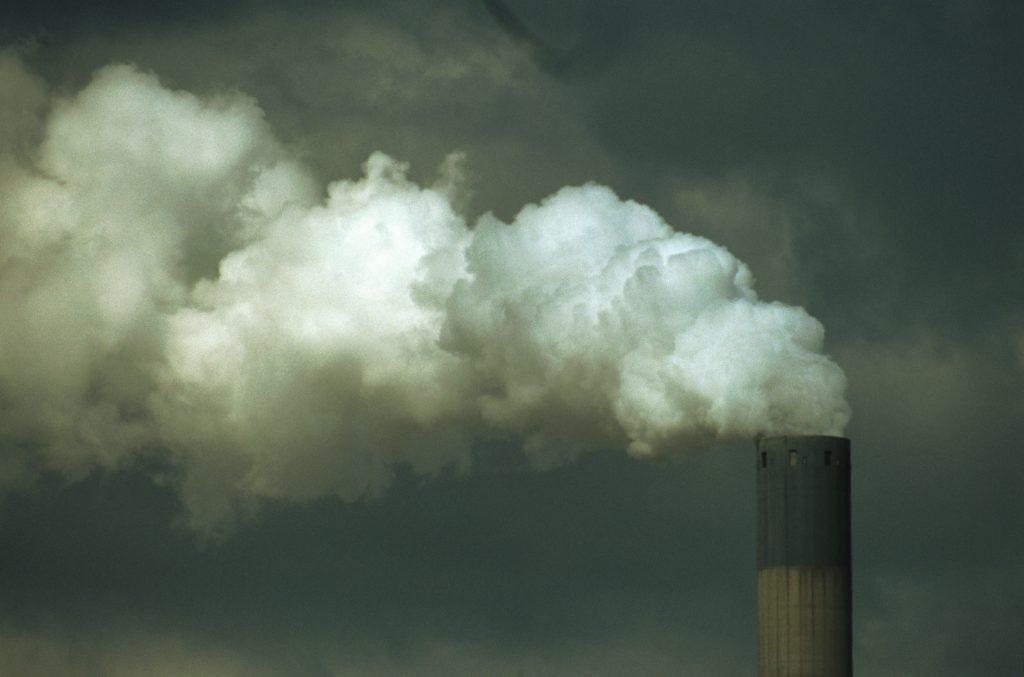
VOC exist naturally in the atmosphere through processes including vegetation growth and soil activity, as well as in biomass burning. However, a significant portion of VOC build-up in the atmosphere come from man-made sources; these include emissions from road traffic and from chemical processes such as crude oil cracking; and products that emit high concentrations of VOCs (for example, paint, solvents and varnishes).

Effects of VOCs on human health

The effects of VOC emissions on human health varies widely according to context. Some VOCs are harmless, but many are toxic at low levels, while others are flammable at higher concentrations. Repeated and long-term, low-level exposure to harmful VOCs can cause serious health issues. For example, formaldehyde, styrene, benzene and other aromatics are known carcinogens – thus, exposure to traffic exhaust fumes, smoking and strong solvents can present serious health risks. Growing awareness of the chronic toxicity of VOCs has led to reduced occupational exposure limits (OEL) and increased requirements for direct measurement.

You can read more about the dangers of VOCs in our white paper.

Environmental issues caused by VOCs

Aside from adverse health implications, the emission of VOCs into the atmosphere causes serious environmental issues. One of these is the formation of ground-level ozone, which leads to smog.

Normally, ozone (or O3) is naturally formed at high altitude in the atmosphere (stratosphere) when O2 molecules are separated into individual oxygen particles by UV radiation. These free oxygen particles then collide with other O2 molecules to become ozone. While we know that ozone helps to protect our planet from the sun’s harmful UV rays, tropospheric, or ground-level, ozone is not emitted directly into the air, but is created by chemical reactions between oxides of nitrogen (NOx) and volatile organic compounds (VOCs).

Here is an example of how nitrogen dioxide can lead to the creation of ozone:

NO2 + Sunlight (UV rays) = NO + O

The free oxygen particle then attaches itself to an O2 molecule and becomes ozone. This happens when pollutants emitted by vehicles, power plants, chemical plants and other sources chemically react in the presence of sunlight. Breathing ozone can cause respiratory irritation and may exacerbate respiratory diseases such as bronchitis and asthma. Ozone at ground-level is hazardous to plants and negatively affects crops.

In addition to ground-level ozone formation, some VOCs may cause odour problems, due to their high odour intensity. Processes like waste incineration, food processing and wastewater treatment emit lots of malodorous gases and are often subject to odour nuisance complaints from nearby residents. Foul smelling gases including H2S, NH3 and VOCs are a significant problem for many industries, including the pharmaceutical, food and beverage, textile and tannery sectors.

At high concentrations, foul-smelling VOCs can cause dizziness and respiratory issues. For this reason, regulations are in place to reduce VOCs in ambient air.

Directives and regulations on VOC emission

Most countries have directives and regulations on VOC emission. In Europe, the relevant directives on atmospheric pollutants, including VOC emissions, are 2001/81/EC and 2016/2284. The first directive sets national emissions ceilings for the VOC emission from all sources, which were to be reached by the year 2010. The second directive specifies the percentage reduction in VOC emissions, both for the individual country and the EU as an entire area.

In addition to outdoor VOC emissions, many countries have implemented regulations to limit the use of VOCs in consumer products. In the EU, Directive 2004/42/EC specifies emission limits for VOCs, prompted by the use of organic solvents in decorative paints and varnishes and in vehicle refinishing products. The directive sets the maximum permissible contents of VOCs in g/L. The directive also requires that suppliers label the subcategory of the product, defines the legal limit value for VOC contents and gives the maximum content of VOC permissible for the product in its ready-to-use condition.
In our next blog we will discuss Crowcon’s unique solution for VOC detection in ambient air.
References
1. Odor-causing volatile organic compounds in wastewater treatment plant units and sludge management areas (J Environ Sci Health A Tox Hazard Subst Environ Eng. 2008 Nov)
2. Ground-level ozone basics (US Environmental Protection Agency guide)
3. Do volatile organic compounds smell? (Foobot website)
4. Volatile organic compounds (VOC) and consumer products regulations (Chem Safety Pro website)
5. Effective and sustainable VOC removal with ozone and AOP (Ozonetech website)

Improving Hydrogen Leak Detection to Increase PEM Fuel Cell & Electrolysis Efficiency

Co-edited by Alicat & Crowcon

Amidst the global push for sustainable, carbon neutral energy sources, many corporations and countries are increasingly interested in alternative fuels. One such fuel is hydrogen, playing a vital role in the clean energy landscape as a green alternative to natural gas. This has resulted in a sudden increased interest in fuel cell and electrolysis technology.

One of the primary challenges facing both of these processes is hydrogen leakage. Hydrogen gas requires careful control on the input side of PEM fuel cell stacks and on the output side of electrolysis.  Any leakage that occurs not only diminishes efficiency, but also raises costs and introduces potential hazards such as flammability and asphyxiation.

Here we discuss hydrogen leak detection in more detail and provide several solutions to help improve the safety and efficiency of fuel cell processes.

Why hydrogen leaks in fuel cells

H2 gas has a high propensity to leak due to its very small size and its low density (0.09 g/L at NTP of 0°C / 1 atm) which corresponds to a high buoyancy.

In fuel cell stacks, hydrogen is prone to leak from seals present at process connections near the H2 storage cylinders and associated flow paths. While it is nearly impossible to reach 100% gas containment in a fuel cell stack, reliable leak detection is essential for minimizing loss.

Detecting hydrogen leaks is critical to maintaining process & personnel safety

Not only does leakage decrease process efficiency, but it becomes a serious safety concern. Hydrogen has a Lower Explosive Limit (LEL) of just 4% volume, meaning even tiny quantities of H2 can cause explosions when mixed with atmospheric air. Even a spark of static electricity from a person’s finger is enough to trigger an explosion when hydrogen is present.

Since hydrogen is odorless, colorless, and tasteless, hydrogen leak detection is extremely difficult without the help of mechanical sensors. Monitoring H2 therefore demands specialized equipment to alert personnel of danger and prompt emergency response procedures.

Detecting hydrogen with traditional sensor technology

Traditional sensor technologies for flammable gas detection are pellistors. Their key disadvantage is that they require oxygen, making them unsuitable in some installations. Another challenge is that some applications put pellistors at risk of being poisoned or inhibited, leaving workers unprotected. These sensors are not fail-safe, and a failure will not be detected unless test gas is applied, commonly known as a bump test.

Detection with mass flow instruments

Hydrogen leak detection relies on in-line process instruments and careful monitoring of system inputs and outputs. For PEM electrolysis, one method involves comparing the mass flow rates of H2O input and hydrogen output to calculate the amount of leakage occurring during the process. Coriolis instruments are ideal for measuring and controlling the input H2O for such electrolysis systems.

Fuel cell stack leak check test bench

Figure 1. Fuel cell stack leak check test bench

For PEM fuel cell stack systems, one common hydrogen leak detection method involves employing a combination of hydrogen sensors alongside flow meters. A flow meter situated downstream of the H2 supply and measurements can be used in conjunction with hydrogen sensors to detect any leaks on the anode side of a PEM fuel cell stack.

Differential pressure based mass flow instruments enable rapid response times, allowing real time leak detection. Given their sensitivity, they are also able to measure very small leaks with high precision and accuracy. This can help identify points of leakage to improve overall process efficiency, decrease cost, and reduce risks of danger to operators.

Detection with MPS™ technology

Crowcon's Xgard Bright

Figure 2. Crowcon’s Xgard Bright

Crowcon, another Halma company, also has a wide range of products for the detection of hydrogen. The Xgard Bright utilizes their latest technology, the Molecular Property Spectrometer (MPS™), to detect and measure ambient levels of hydrogen and other flammable gases with high-accuracy and precision in real time. Furthermore, the sensors do not require recalibration, significantly reducing total cost of ownership and limiting interaction with the units. The Xgard Bight ensures process operators are at no risk of being poisoned while also guaranteeing no false alarms.

Alicat, Crowcon, and the Halma family of brands are here to provide solutions to help create a safer, cleaner, healthier world.

How Hydrogen is Helping the Gas and Steel Industries to Go Green

Green hydrogen, taken from both low carbon and renewable energy sources, can play a crucial role in taking a company – or a country – closer to carbon neutrality. Common applications in which green hydrogen can be used include:

  • Fuel cells for electric vehicles
  • As the hydrogen in pipeline gas blending
  • In ‘green steel’ refineries that burn hydrogen as a heat source rather than coal
  • In container ships powered by liquid ammonia that is made from hydrogen
  • In hydrogen-powered electricity turbines that can generate electricity at times of peak demand

This post will explore the use of hydrogen in pipeline gas blending and green steel refineries.

Injecting hydrogen into pipelines

Governments and utilities companies worldwide are exploring the possibilities of injecting hydrogen into their natural gas grids, to reduce fossil fuel consumption and limit emissions. Indeed, hydrogen injection into pipelines now features in the national hydrogen strategies of the EU, Australia and the UK, with the EU’s hydrogen strategy specifying the introduction of hydrogen into national gas grids by 2050.

From an environmental point of view, adding hydrogen to natural gas has the potential to significantly reduce greenhouse gas emissions, but to achieve that, the hydrogen must be produced from low-carbon energy sources and renewables. For example, hydrogen generated from electrolysis, bio-waste or fossil fuel sources that use carbon capture and storage (CCS).

In a similar way, countries aspiring to develop a green hydrogen economy can turn to grid injection to stimulate investment and develop new markets. In an effort to kick start its renewable hydrogen plan, Western Australia is planning to introduce at least 10% renewable hydrogen into its gas pipelines and networks, and to bring forward the state’s targets under its renewable hydrogen strategy from 2040 to 2030.

On a volumetric basis, hydrogen has a much lower energy density than natural gas, so end-users of a blended gas would require a higher volume of gas to achieve the same heating value as those using pure natural gas. Simply put, a 5% blending of hydrogen by volume does not directly translate into a 5% reduction in fossil fuel consumption.

Is there any safety risk in hydrogen blending in our gas supply? Let’s examine the risk:

  1. Hydrogen has lower LEL than natural gas, so there is a higher risk of generating a flammable atmosphere with blended gas mixtures.
  2. Hydrogen has lower ignition energy than natural gas and a broad flammable range (4% to 74% in air), so there is higher risk of explosion
  3. Hydrogen molecules are small and move quickly, so any blended gas leak will spread faster and wider than would be the case with natural gas.

In the UK, domestic and industrial heating accounts for half of the UK’s energy consumption and one third of its carbon emissions. Since 2019, the UK’s first project to inject hydrogen into the gas grid has been underway, with trials taking place at Keele University. The HyDeploy project aims to inject up to 20% hydrogen and blend it with the existing gas supply to heat residential blocks and campuses without changing the gas-fired appliances or piping. In this project, Crowcon gas detectors and flue gas analyser are being used to identify the impact of hydrogen blending in terms of gas leak detection. Crowcon’s Sprint Pro flue gas analyser is being used to assess for boiler efficiency.

Crowcon’s Sprint Pro is a professional grade flue gas analyser, with features tailored to meet the needs of the HVAC professional, a robust design, full selection of accessories and 5-year warranty. Read more about the Sprint Pro here.

Hydrogen in the steel industry

Traditional iron and steel production is considered one of the largest emitters of environmental pollutants, including greenhouse gases and fine dust. Steel making processes rely heavily on fossil fuels, with coal products accounting for 78% of these. It is thus not surprising that the steel industry emits around 10% of all global process- and energy-related CO2 emissions.

Hydrogen may be an alternative for steel companies seeking to drastically reduce their carbon emissions. Several steel makers in Germany and Korea are already cutting emissions through a hydrogen reduction steelmaking method that uses hydrogen, not coal, to make steel. Traditionally, a significant amount of hydrogen gas is produced in steel making as a by-product called coke gas. By passing that coke gas through a process called carbon capture and storage (CCS), steel plants can produce significant amount of blue hydrogen, which can then be used to control temperatures and prevent oxidation during steel production.

In addition, steel makers are producing steel products specifically for hydrogen. As part of its new vision of becoming a green hydrogen enterprise, Korean steelmaker POSCO has invested heavily to develop steel products for use in the production, transport, storage and utilisation of hydrogen.

With many flammable and toxic gas hazards being present in steel plants, it is important to understand the cross sensitivity of gases, because a false gas reading could prove fatal. For example, a blast furnace produces a great deal of hot, dusty, toxic and flammable gas consisting of carbon monoxide (CO) with some hydrogen. Gas detection manufacturers that have experience in these environments are well acquainted with the issue of hydrogen affecting electrochemical CO sensors, and thus provide hydrogen-filtered sensors as standard to steel facilities.

To learn more about cross sensitivity, please see our blog. Crowcon gas detectors are used in many steel facilities across the world, and you can find out more about Crowcon solutions in the steel industry here.

References:

  1. Injecting hydrogen in natural gas grids could provide steady demand the sector needs to develop (S&P Global Platts, 19 May 2020)
  2. Western Australia pumps $22m into hydrogen action plan (Power Engineering, 14 Sep 2020)
  3. Green Hydrogen in Natural Gas Pipelines: Decarbonization Solution or Pipe Dream? (Green Tech Media, 20 Nov 2020)
  4. Could hydrogen piggyback on natural gas infrastructure? (Network Online, 17 Mar 2016)
  5. Steel, Hydrogen and Renewables: Strange Bedfellows? Maybe Not… (Forbes.com, 15 May 2020)
  6. POSCO to Expand Hydrogen Production to 5 Mil. Tons by 2050 (Business Korea, 14 Dec 202 0)http://https://www.crowcon.com/wp-content/uploads/2020/07/shutterstock_607164341-scaled.jpg

How to correctly sample gases using pumped instruments

In many situations, workers must perform pre-entry gas checks, to make sure that a confined space is safe before entering. This is often a requirement arising from risk assessment or to allow the issuing of permits to work, or is simply needed because the area is inherently risky. Whatever the reason, using a pumped device in conjunction with a sampling tube is a great way to perform pre-entry checks to check that a confined space is safe before entry.

However, taking measurements in this way brings its own set of challenges and dangers, and when using Crowcon products in pumped or manual sampling modes, all operators should take care to follow these instructions:

• It is strongly recommended that, before proceeding, a function check is performed using the pump and sample tube with the gas/vapour to be detected.

• To reduce the risk of absorption of the gas/vapour in the sample tube, ensure the temperature of the sampling tube is above the flashpoint temperature of the target vapour.

• Ensure the monitor is correctly calibrated for the target gas/vapour.

• Only use the sample tube supplied by Crowcon. It is strongly recommended that ‘reactive gas tubing’ (part no. AC0301) is used for sampling gases/vapours that are likely to be adsorbed (for example, toluene, chlorine, ammonia, hydrogen sulphide, ozone, hydrogen chloride, NOx, etc).

• Keep the sample tube length as short as possible.

• Please allow sufficient time for the gas/vapour to reach the sensor; allow at least 3 seconds per metre plus the normal T90 response time of the sensor (typically 30–40 seconds).

In addition, please note that some of the gases that can be measured by our gas detection products are classified as ‘reactive’ gases.

A reactive gas will react with, or be absorbed by, the material(s) with which it comes into contact. As a result, the gas concentration reaching the sensor can be reduced, leading to an incorrect reading.

The following list includes some (but not all) reactive gases, which are listed with the appropriate calibration gas. Please contact Crowcon for specific gas concentration information and cross-calibration values).

Target Gas Calibration Gas
Ozone (O3) Ozone (via O3 generator)
Hydrogen Chloride (HCL) Hydrogen Chloride
Hydrogen Fluoride (HF) Hydrogen Chloride or Sulphur Dioxide
Chlorine (Cl2) Chlorine (via Cl2 generator)
Fluorine (F2) Chlorine (via Cl2 generator)
Chlorine Dioxide (ClO2) Chlorine (via Cl2 generator
Phosgene (COCl2) Chlorine (via Cl2 generator)
Sulphur Dioxide (SO2) Sulphur Dioxide
Nitrogen Dioxide (NO2) Nitrogen Dioxide
Nitrogen Monoxide (NO) Nitrogen Monoxide
Ammonia (NH3) Ammonia

• It is very important that the appropriate accessories and precautions are applied when measuring, calibrating or bump testing sensors that are targeting reactive gasses

When taking sample measurements:

• Use Teflon, FEP or PTFE tubing; the tube length must be kept as short as possible (<50 cm). Avoid connectors and unions.
• Allow the sample to flow through the regulator/pipe for at least 3 minutes, for initial absorption to occur, before attempting to get a reading.

When calibrating the above points apply in addition to the following:

• The recommended gas flow-rate is 0.5 litres per minute.
• Gas generators are recommended, instead of gas cylinders, for some very unstable gases, especially where very low ppm concentrations are required.
• Use only stainless steel regulators for cylinder gas.
• Ensure the correct calibration adaptor is used, appropriate to the specific product.

Following the above guidance will allow your pumped devices pre-entry checks to deliver accurate measurements – even with reactive gasses – and will keep staff safe and well.

TWA Resume – how Crowcon’s patented feature keeps workers safe and makes compliance easier

Most people who work with hazardous gases, and particularly anyone with responsibility for regulatory compliance, will be familiar with the various ways of measuring workplace exposures to gas. You may have heard of short- and long-term exposure limits; these are used to quantify the amount of gas a worker can be exposed to without harm, and most gas detectors track them.

But why differentiate between a short-term and long-term exposure? Well, that has mainly to do with the ways in which gases can be harmful. Some gases (hydrogen cyanide, for example) can be almost immediately fatal if inhaled at a given concentration, but some gases remain harmless if present at or below a much lower level for extended periods of time.

If a worker’s long-term exposure is more than the safe level, however, then some gases can be seriously dangerous to health. And the company in charge may become legally liable because it will have failed to comply with gas regulations.

Non-compliance can get very expensive, very quickly. It is costly in both financial and reputational terms.

Figure 1: This image shows how Crowcon’s proprietary TWA Resume feature keeps workers safe and proves a firm’s compliance, by continuing to monitor exposure to harmful gases even after a mid-shift break or other switch-off during the TWA period. Other detectors don’t do this, they assume any switch-off (e.g. for meals or to drive between sites) signals a new period of measurement, which leaves workers vulnerable to over-exposure and harm, and firms open to legal sanctions due to harm and/or non-compliance. In this image, you can see the workplace exposure limit is breached at around 14:00, but only the Crowcon device with TWA Resume alerts the user to this fact and documents it.

Why use TWAs?

Long-term and short-term workplace exposure limits (WELs) for gases are set out by local regulatory bodies. In the UK, the HSE document EH40 applies. Chronic exposure is often measured via a time-weighted average, or TWA. That means the worker’s exposure to a gas is monitored across a given period, usually 8 hours, to make sure the gas(es) remain(s) at or below the WEL throughout that time.

Unfortunately, it is incredibly easy to mess up a TWA measurement and thus fall foul of the regulations. This is because many standard gas detectors erase the TWA timer history when they are switched off, even if the 8-hour/TWA measurement period is ongoing. So, if an operator turns off one of these detectors because they are having lunch or moving between sites, then switches it back on again when they get back to work (bearing in mind this is a continuation of the TWA period they have already begun to track), the detector will assume that they are beginning a new TWA measurement period.

Clearly, this breaches regulations and can be very dangerous – Figure 1, above, shows why. In this example, the worker exceeds the safe limit at around 14:00 but the traditional device does not ‘see’ this or alert them. The Crowcon device with TWA Resume, however, does sound the alert. And that may save both the worker and the company from a great deal of harm.

What is TWA Resume?

The Crowcon T4 and Gas-Pro ranges have Crowon’s proprietary TWA Resume feature. This  innovative and unique functionality makes sure accurate TWAs are recorded for each and every 8-hour/TWA period, keeping employees safe and removing the risk of non-compliance. Furthermore, it makes it easy for a firm to prove their compliance in the face of any legal claim.

TWA Resume is a patented feature only found on Crowcon devices. When turned off during the TWA measurement period, it stores TWA data in its memory. When a worker switches it back on, they can choose to resume measurement from where it left off, or start a new TWA measurement.

T4 and Gas-Pro detectors store this data in their logs, where is available for further analysis and to prove compliance. Even better, TWA alarms and near-miss data can now be easily exported into Crowcon Connect, a cloud-based portal that gives customers total data visibility. This makes it easy for them to prove compliance, and to be sure that their workers are safe.

Because TWA Resume is a patented Crowcon feature, only Crowcon can provide it. If you want to keep your staff safe while making regulatory compliance much easier, please contact us. We’ll be happy to give you more information on our patented TWA resume feature and discuss how it can help you and your business.

Are you safe to re-start operations?

As governments around the world ease lockdown measures that were introduced to combat Covid-19, many of us are starting to plan how to return to business. But re-starting operations after a break can present specific gas-related problems and dangers that must be dealt with before operations begin.

A terrible example of what can happen otherwise has recently occurred in India. There, a persistent styrene leak, from a factory that had been closed due to the Covid-19 outbreak, killed at least 11 people, and harmed many more within a radius of several kilometres.

The need to check gas safety after a break in operations applies across many sectors. These include:

-Car plants

-Manufacturing facilities of all types

-Bars, restaurants and hospitality venues

-Leisure centres and swimming pools

-Refineries and chemical processing plants, where operations have been scaled back or stopped due to reduced demand

-Laboratories

-Schools and colleges

-General industrial sites that ceased operations due to Covid-19.

What are the dangers?

While the challenges arising will vary by sector, the most common include:

  • Re-pressurisation of systems. Many industries – from schools and colleges to bars and oil refineries – use pressurised systems or equipment such as boilers, steam heating systems, autoclaves, pipework, heat exchangers and refrigeration plant. If these are not correctly pressurised, they may explode, leak or cause contact injuries Any break in operations may have caused or coincided with a change (usually a drop) in pressure.

Some systems contain gases that are inherently toxic/flammable, some gases may be safe in normal process conditions but are now less safe due to changes in pressure or other conditions created by a recent shut-down. In any case, there is a legal duty to maintain pressurised systems (you can find out more from the HSE’s pages here) so it makes sense to check the system before re-starting operations, and to re-pressurise the system if required.

  • Areas used to store toxic and/or flammable gases that have not been entered for some time. This is likely to be a widespread danger because such areas are not always industrial. Swimming pool operators store chlorine; cafes, schools and colleges store gases for educational and catering purposes; food-makers, pubs and bars use gases in the manufacture and dispensing of beverages. If gas has leaked during a Covid-19 shut-down, it may endanger property and staff when operations begin again. Alternatively, the break could mean that gases are no longer stored at their optimum pressure or temperature.
  • It should also be noted that some stored goods may emit toxic or flammable gases if they have been left for a long period. For example, methane and hydrogen sulphide may be generated by organic matter that has begun to degrade or ferment.
  • Re-starting production or operations where materials/chemicals have been left unattended for some time can also be hazardous. For example, anything stored at a specific pressure may have experienced a change in that pressure, and materials stored in sub-optimal conditions (e.g. in terms of ambient temperature, pressure, exposure to light or operation) may now be unfit for purpose or even dangerous.

What should I do before re-starting operations?

Gas hazards should form part of your re-starting operations risk assessment.

When it comes to gas, Crowcon has a wealth of knowledge gathered over many years and from many installations. If you need reliable information about the gas-related dangers that may arise on your own return to operations, check out our ‘Talking Gas’ information hub, which is full of free resources to download, and our ‘Insights’ knowledge base. And if you have any other questions relating to the post-Covid return, please get in touch.


What’s the difference between a pellistor and an IR sensor?

Sensors play a key role when it comes to monitoring flammable gases and vapours. Environment, response time and temperature range are just some of the things to consider when deciding which technology is best.

In this blog, we’re highlighting the differences between pellistor (catalytic) sensors and infrared (IR) sensors, why there are pros and cons to both technologies, and how to know which is best to suit different environments.

Pellistor sensor

A pellistor gas sensor is a device used to detect combustible gases or vapours that fall within the explosive range to warn of rising gas levels. The sensor is a coil of platinum wire with a catalyst inserted inside to form a small active bead which lowers the temperature at which gas ignites around it. When a combustible gas is present the temperature and resistance of the bead increases in relation to the resistance of the inert reference bead. The difference in resistance can be measured, allowing measurement of gas present. Because of the catalysts and beads, a pellistor sensor is also known as a catalytic or catalytic bead sensor.

Originally created in the 1960’s by British scientist and inventor, Alan Baker, pellistor sensors were initially designed as a solution to the long-running flame safety lamp and canary techniques. More recently, the devices are used in industrial and underground applications such as mines or tunnelling, oil refineries and oil rigs.

Pellistor sensors are relatively lower in cost due to differences in the level of technology in comparison to IR sensors, however they may be required to be replaced more frequently.

With a linear output corresponding to the gas concentration, correction factors can be used to calculate the approximate response of pellistors to other flammable gases, which can make pellistors a good choice when there are multiple flammable vapours present.

Not only this but pellistors within fixed detectors with mV bridge outputs such as the Xgard type 3 are highly suited to areas that are hard to reach as calibration adjustments can take place at the local control panel.

On the other hand, pellistors struggle in environments where there is low or little oxygen, as the combustion process by which they work, requires oxygen. For this reason, confined space instruments which contain catalytic pellistor type LEL sensors often include a sensor for measuring oxygen.

In environments where compounds contain silicon, lead, sulphur and phosphates the sensor is susceptible to poisoning (irreversible loss of sensitivity) or inhibition (reversible loss of sensitivity), which can be a hazard to people in the workplace.

If exposed to high gas concentrations, pellistor sensors can be damaged. In such situations, pellistors do not ‘fail safe’, meaning no notification is given when an instrument fault is detected. Any fault can only be identified through bump testing prior to each use to ensure that performance is not being degraded.


IR sensor

Infrared sensor technology is based on the principle that Infrared (IR) light of a particular wavelength will be absorbed by the target gas. Typically there are two emitters within a sensor generating beams of IR light: a measurement beam with a wavelength that will be absorbed by the target gas, and a reference beam which will not be absorbed. Each beam is of equal intensity and is deflected by a mirror inside the sensor onto a photo-receiver. The resulting difference in intensity, between the reference and measurement beam, in the presence of the target gas is used to measure the concentration of gas present.

In many cases, infrared (IR) sensor technology can have a number of advantages over pellistors or be more reliable in areas where pellistor-based sensor performance can be impaired- including low oxygen and inert environments. Just the beam of infrared interacts with the surrounding gas molecules, giving the sensor the advantage of not facing the threat of poisoning or inhibition.

IR technology provides fail-safe testing. This means that if the infrared beam was to fail, the user would be notified of this fault.

Gas-Pro TK uses a dual IR sensor – the best technology for the specialist environments where standard gas detectors just won’t work, whether tank purging or gas freeing.

An example of one of our IR based detectors is the Crowcon Gas-Pro IR, ideal for the oil and gas industry, with the availability to detect methane, pentane or propane in potentially explosive, low oxygen environments where pellistor sensors may struggle. We also use a dual range %LEL and %Volume sensor in our Gas-Pro TK, which is suitable for measuring and switching between both measurements so it’s always safely operating to the correct parameter.

However, IR sensors aren’t all perfect as they only have a linear output to target gas; the response of an IR sensor to other flammable vapours then the target gas will be non-linear.

Like pellistors are susceptible to poisoning, IR sensors are susceptible to severe mechanical and thermal shock and also strongly affected by gross pressure changes. Additionally, infrared sensors cannot be used to detect Hydrogen gas, therefore we suggest using pellistors or electromechanical sensors in this circumstance.

The prime objective for safety is to select the best detection technology to minimise hazards in the workplace. We hope that by clearly identifying the differences between these two sensors we can raise awareness on how various industrial and hazardous environments can remain safe.

For further guidance on pellistor and IR sensors, you can download our whitepaper which includes illustrations and diagrams to help determine the best technology for your application.

You won’t find Crowcon sensors sleeping on the job

MOS (metal oxide semiconductor) sensors have been seen as one of the most recent solutions for tackling detection of hydrogen sulphide (H2S) in fluctuating temperatures from up to 50°C down to the mid-twenties, as well as humid climates such as the Middle East.

However, users and gas detection professionals have realised MOS sensors are not the most reliable detection technology. This blog covers why this technology can prove difficult to maintain and what issues users can face.

One of the major drawbacks of the technology is the liability of the sensor “going to sleep” when it doesn’t encounter gas for a period of time. Of course, this is a huge safety risk for workers in the area… no-one wants to face a gas detector that ultimately doesn’t detect gas.

MOS sensors require a heater to equalise, enabling them to produce a consistent reading. However, when initially switched on, the heater takes time to warm up, causing a significant delay between turning on the sensors and it responding to hazardous gas. MOS manufacturers therefore recommend users to allow the sensor to equilibrate for 24-48 hours before calibration. Some users may find this a hinderance for production, as well as extended time for servicing and maintenance.

The heater delay isn’t the only problem. It uses a lot of power which poses an additional issue of dramatic changes of temperature in the DC power cable, causing changes in voltage as the detector head and inaccuracies in gas level reading. 

As its metal oxide semiconductor name suggests, the sensors are based around semiconductors which are recognised to drift with changes in humidity- something that is not ideal for the humid Middle Eastern climate. In other industries, semiconductors are often encased in epoxy resin to avoid this, however in a gas sensor this coating would the gas detection mechanism as the gas couldn’t reach the semiconductor. The device is also open to the acidic environment created by the local sand in the Middle East, effecting conductivity and accuracy of gas read-out.

Another significant safety implication of a MOS sensor is that with output at near-zero levels of H2S can be false alarms. Often the sensor is used with a level of “zero suppression” at the control panel. This means that the control panel may show a zero read-out for some time after levels of H2S have begun to rise. This late registering of low-level gas presence can then delay the warning of a serious gas leak, opportunity for evacuation and the extreme risk of lives.

MOS sensors excel in reacting quickly to H2S, therefore the need for a sinter counteracts this benefit. Due to H2S being a “sticky” gas, it is able to be adsorbed onto surfaces including those of sinters, in result slowing down the rate at which gas reaches the detection surface.

To tackle the drawbacks of MOS sensors, we’ve revisited and improved on the electrochemical technology with our new High Temperature (HT) H2S sensor for XgardIQ. The new developments of our sensor allow operation of up to 70°C at 0-95%rh- a significant difference against other manufacturers claiming detection of up to 60°C, especially under the harsh Middle Eastern environments.

Our new HT H2S sensor has been proven to be a reliable and resilient solution for the detection of H2S at high temperatures- a solution that doesn’t fall asleep on the job!

Click here for more information on our new High Temperature (HT) H2S sensor for XgardIQ.

An ingenious solution to the problem of high temperature H2S

Due to extreme heat in the Middle East climbing up to 50°C in the height of summer, the necessity for reliable gas detection is critical. In this blog, we’re focusing on the requirement for detection of hydrogen sulphide (H2S)- a long running challenge for the Middle East’s gas detection industry.

By combining a new trick with old technology, we’ve got the answer to reliable gas detection for environments in the harsh Middle Eastern climate. Our new High Temperature (HT) H2S sensor for XgardIQ has been revisited and improved by our team of Crowcon experts by using a combination of two ingenious adaptations to its original design.

In traditional H2S sensors, detection is based on electrochemical technology, where electrodes are used to detect changes induced in an electrolyte by the presence of the target gas. However, high temperatures combined with low humidity causes the electrolyte to dry out, impairing sensor performance so that the sensor has to be replaced regularly; meaning high replacement costs, time and efforts.

Making the new sensor so advanced from its predecessor is its ability to retain the moisture levels within the sensor, preventing evaporation even in high temperature climates. The updated sensor is based on electrolytic gel, adapted to make it more hygroscopic and avoiding dehydration for longer.

As well as this, the pore in the sensor housing has been reduced, limiting the moisture from escaping. This chart indicated weight loss which is indicative of moisture loss. When stored at 55°C or 65°C for a year just 3% of weight is lost. Another typical sensor would lose 50% of its weight in 100 days in the same conditions.

For optimal leak detection, our remarkable new sensor also features an optional remote sensor housing, while the transmitter’s displays screen and push-button controls are positioned for safe and easy access for operators up to 15metres away.


The results of our new HT H2S sensor for XgardIQ speak for themselves, with an operating environment of up to 70°C at 0-95%rh, as well featuring a 0-200ppm and T90 response time of less than 30 seconds. Unlike other sensors for detecting H2S, it offers a life expectancy of over 24 months, even in tough climates like the Middle East.

The answer to the Middle East’s gas detection challenges fall in the hands of our new sensor, providing its users with cost-effective and reliable performance.

Click here for more information about the Crowcon HT H2S sensor.

Have you ever thought about the dangers behind your favourite beverage?

Beer Production

It’s only natural for us to associate the need for gas detection in the oil and gas, and steel industries, but have you thought about the need to detect hazardous gases such as carbon dioxide and nitrogen in the brewing and beverage industry?

Maybe it’s because nitrogen (N2) and carbon dioxide (CO2) are naturally present in the atmosphere. It could be that CO2 is still under-valued as a hazardous gas. Although in the atmosphere CO2 remains at very low concentrations – around 400 parts per million (ppm), greater care is needed in brewery and cellar environments where in confined spaces, the risk of gas canisters or associated equipment leaking could lead to elevated levels. As little as 0.5% volume (5000ppm) of CO2 is a toxic health hazard. Nitrogen on the other hand, can displace oxygen.

CO2 is colourless, odourless and has a density which is heavier than air, meaning pockets of CO2 gather low on the ground gradually increasing in size. CO2 is generated in huge amounts during fermentation and can pose a risk in confined spaces such as vats, cellars or cylinder storage areas, this can be fatal to workers in the surrounding environment, therefore Health & Safety managers must ensure the correct equipment and detectors are in place.

Brewers often use nitrogen in multiple phases of the brewing and dispensing process to put bubbles into beer, particularly stouts, pale ales and porters, it also ensures the beer doesn’t oxidise or pollute the next batch with harsh flavours. Nitrogen helps push the liquid from one tank to another, as well as offer the potential to be injected into kegs or barrels, pressurising them ready for storage and shipment. This gas is not toxic, but does displace oxygen in the atmosphere, which can be a danger if there is a gas leak which is why accurate gas detection is critical.

Gas detection can be provided in the form of both fixed and portable. Installation of a fixed gas detector can benefit a larger space such as plant rooms to provide continuous area and staff protection 24 hours a day. However, for worker safety in and around cylinder storage area and in spaces designated as a confined space, a portable detector can be more suited. This is especially true for pubs and beverage dispensing outlets for the safety of workers and those who are unfamiliar in the environment such as delivery drivers, sales teams or equipment technicians. The portable unit can easily be clipped to belts or clothing and will detect pockets of CO2 using alarms and visual signals, indicating that the user should immediately vacate the area.

At Crowcon, we’re dedicated in growing a safer, cleaner, healthier future for everyone, every day by providing best in class gas safety solutions. It’s vital that once gas detectors are deployed, employees should not get complacent, and should be making the necessary checks an essential part of each working day as early detection can be the difference between life and death.

Quick facts and tips about gas detection in breweries:

  • Nitrogen and CO2 are both colourless and odourless. CO2 being 5 times heavier than air, making it a silent and deadly gas.
  • Anyone entering a tank or other confined space must be equipped with a suitable gas detector.
  • Early detection can be the difference between life and death.